


TL;DR / Key Takeaways
- Voltage drop on long wire runs is the single most common electrical cause of a 24V solenoid failing to energize; always measure voltage at the valve terminals, not at the controller.
- Debris lodged in the pilot orifice of a hydraulically driven diaphragm valve can block operation even when the solenoid coil is electrically sound.
- Coil burnout from sustained over-voltage or moisture ingress accounts for roughly a third of field failures in hot, humid climates.
- Water hammer pressure spikes can fatigue and crack diaphragms over time, causing intermittent or total valve failure.
- Incorrect valve orientation or reversed flow direction during installation prevents the diaphragm from responding to pilot pressure changes.
- Using a true-RMS multimeter and following a systematic voltage-to-mechanical diagnostic sequence eliminates guesswork on site.
- Preventive biannual inspections with logged voltage readings catch gradual degradation before it becomes a costly field call.
1. How a 24V Solenoid Valve Functions in a Landscape Irrigation System
Before a technician can diagnose why a solenoid valve has failed to open, it helps to understand exactly what happens inside the valve when the irrigation controller sends its 24-volt signal. In a hydraulically driven diaphragm design, such as the Inovato YT210 T-Type Solenoid Valve series, the solenoid does not directly push water through the body. Instead, the coil energizes a small plunger that lifts off a pilot seat, allowing trapped water above the diaphragm to bleed downstream. Once the pressure above the diaphragm drops below the inlet pressure, the diaphragm flexes upward and the main waterway opens.
The 24-volt rating appears on most commercial landscape controllers worldwide because it provides a safe, low-voltage signal that can travel over standard irrigation wire without posing an electrocution hazard to groundskeeping staff. The Inovato 3W-24VAC/24VDC Mechanical Solenoid is designed to accept either alternating or direct current at 24 volts, giving installers flexibility when matching solenoids to controllers from different manufacturers. Regardless of whether the signal is AC or DC, the underlying electromagnetic principle is the same: current flows through the coil winding, creates a magnetic field, and pulls the ferromagnetic plunger into the coil bore against a return spring.
This two-stage process, electrical-to-magnetic-to-hydraulic, means there are multiple points where a failure can prevent the valve from opening. A fault in the wiring, the coil, the plunger, the pilot orifice, the diaphragm, or even the pipeline itself can each independently stop the sequence. Understanding where each stage begins and ends gives the technician a logical diagnostic path instead of a random trial-and-error approach that wastes time on a busy commercial site. That structured approach is what separates a quick field fix from a frustrating multi-visit callback.
2. Wiring Faults and Electrical Connection Problems
The most frequent electrical cause of a solenoid valve that will not open is a wiring fault somewhere between the irrigation controller and the valve location. On a commercial landscape site, the valve wire often runs through conduit buried under hardscape, passes through junction boxes exposed to moisture, and splices at multiple points before reaching the solenoid leads. Each splice and each junction box is a potential failure point. Corroded wire nuts, loose crimp connectors, and rodent-chewed insulation are common findings when a technician traces a dead circuit.
A systematic approach starts at the controller. Measure the output voltage on the zone terminal while the controller is actively calling for that zone. If the controller shows 24V at its terminal strip, move to the first field junction box and measure again. Continue downstream until the voltage disappears or drops below the solenoid's minimum operating threshold. The point where the signal vanishes identifies the fault location. In many cases, the problem is a single corroded splice in a valve box that has been sitting in standing water for years.
Another common wiring mistake occurs during new installations or renovations when common wires get crossed between zones. If two valve solenoids share a common return wire and that wire is broken, both zones will appear dead. Conversely, if the common wire touches a hot zone wire in a wet junction box, the controller may show an electrical fault or the wrong valve may open intermittently. Labeling both the hot and common wires at every junction box, using waterproof wire connectors rated for direct burial, and testing continuity with the system de-energized are simple practices that prevent most wiring-related valve failures on commercial projects.
3. Voltage Drop on Long Wire Runs
Even when every splice is intact and every connection is clean, a 24V solenoid valve can fail to open simply because the wire run is too long for the conductor gauge being used. Voltage drop is a function of wire resistance multiplied by the current draw of the solenoid. A typical 24VAC Irrigation Solenoid draws between 0.2 and 0.45 amps. On a 14 AWG wire pair, that current produces a modest voltage drop over a few hundred feet. But on an 18 AWG pair running 800 feet across a large commercial property, the drop can exceed six volts, leaving the solenoid with only 17 or 18 volts at its terminals.
The American Society of Agricultural and Biological Engineers (ASABE) publishes guidelines on wire sizing for irrigation systems that account for both voltage drop and the inrush current spike that occurs in the first milliseconds after energization. During that inrush period, the solenoid can draw three to five times its steady-state current, and the corresponding voltage drop is proportionally larger. This is why a solenoid that reads 21V on a steady-state measurement may still fail to open: the brief inrush drop brings the actual available voltage below the pull-in threshold.
Field technicians should carry a wire gauge chart when surveying large commercial sites. If a zone is located at the far end of a property and the existing wire is undersized, the practical solutions include splicing in a heavier gauge wire for the long run segment or switching to a latching solenoid that requires only a brief pulse rather than continuous energization. Choosing the right wire gauge at the design stage, as recommended by the Irrigation Association and in accordance with NEC Article 725 for low-voltage circuits, eliminates this problem before it ever reaches the field.
4. Debris and Sediment Blocking the Diaphragm Pilot Orifice
One of the most deceptive failure modes in a hydraulically driven diaphragm solenoid valve is debris contamination in the pilot orifice. The pilot passage in a valve body such as the Inovato YT210 series is intentionally small, often only two to three millimeters in diameter, because it must restrict the flow of water above the diaphragm to create a controlled pressure differential. That small diameter makes it highly vulnerable to blockage by sand grains, rust flakes, mineral scale, or organic matter that enters the piping system during installation, after a mainline break, or through a compromised filter.
When the pilot orifice is partially or fully blocked, the solenoid coil may energize correctly and the plunger may lift off its seat, but the trapped water above the diaphragm cannot bleed fast enough to create the pressure drop needed for the main valve to open. The technician at the site will measure correct voltage at the terminals and may even hear the plunger click when the zone is activated, yet no water flows downstream. This symptom is frequently misdiagnosed as a bad diaphragm or an undersized valve, leading to unnecessary part replacements and repeat callbacks.
The correct field procedure is to isolate the valve by closing the upstream isolation valve, relieving pressure through the manual bleed screw, and then removing the solenoid bonnet assembly to expose the pilot area. Flushing the pilot passage with clean water and inspecting it with a bright light usually reveals the obstruction. On installations where water quality is poor, installing a fine mesh filter on the inlet side of each valve bank, as recommended in ASABE irrigation engineering standards, significantly reduces the frequency of pilot blockages and extends the service life of every valve on the system.
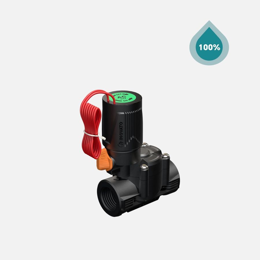
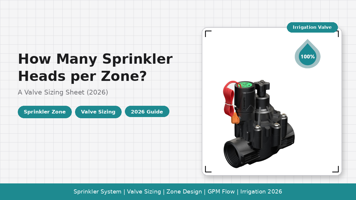
Inovato YT210 T-Type Solenoid Valve with 24V mechanical solenoid, designed for hydraulically driven diaphragm operation in commercial landscape irrigation zones.
5. Coil Burnout and Thermal Degradation
The solenoid coil is the electromechanical heart of the valve, and when it fails, the valve is completely inoperable regardless of water pressure or pipeline condition. Coil burnout occurs when the internal copper winding insulation breaks down due to excessive heat, allowing adjacent turns to short-circuit. Once enough turns are shorted, the coil can no longer generate sufficient magnetic field strength to pull the plunger, and the valve remains closed. The most common causes of coil overheating in landscape irrigation are sustained over-voltage from an improperly regulated power supply, continuous duty operation in a high ambient temperature environment, and moisture intrusion that degrades the winding insulation from the inside.
In hot climates where commercial landscapes are most prevalent, the combination of black valve box covers absorbing solar radiation and ambient air temperatures exceeding 40 degrees Celsius can push coil temperatures well beyond their rated limits. A coil rated for continuous duty at 25 degrees Celsius may only survive intermittent duty at 45 degrees. The Inovato Solenoid Coil product line includes both AC and DC-latching variants, each designed with specific thermal ratings. Selecting the correct coil type for the local climate and duty cycle is a design decision that prevents premature burnout.
Visual inspection is the quickest field diagnostic for coil burnout. A coil that has overheated typically shows discoloration on its housing, a melted or cracked potting compound, or a visible burn mark near the wire leads. Measuring the coil resistance with a multimeter and comparing it to the manufacturer's specification provides confirmation: a reading significantly lower than the rated resistance indicates shorted turns, while an open-circuit reading indicates a completely burned-through winding. In either case, the coil must be replaced. Ensuring that valve boxes are ventilated and that coils are rated for the local temperature extremes per IEC 60730 standards for automatic electrical controls reduces the frequency of thermal failures across an installation.
6. Water Hammer and Hydraulic Pressure Surges
Water hammer is a transient hydraulic phenomenon that occurs when flowing water is suddenly stopped, such as when a downstream zone valve closes or a pump shuts off abruptly. The kinetic energy of the moving water column converts into a pressure wave that travels back through the pipe at the speed of sound in water, which can exceed 1,200 meters per second in steel or PVC piping. This pressure spike can reach five to ten times the normal system operating pressure, and it arrives at the upstream solenoid valve in a matter of milliseconds.
A single water hammer event may not cause immediate valve failure, but repeated surges fatigue the elastomer diaphragm material inside the valve body. Over weeks and months of daily irrigation cycles, micro-tears develop in the diaphragm that compromise its ability to flex and seal properly. The valve may start to exhibit intermittent behavior, opening on some cycles but not others, or it may fail to close completely after a zone run, causing constant downstream flow and water waste. Diagnosing hammer-related diaphragm damage requires removing the valve bonnet and physically inspecting the diaphragm for tears, deformation, or hardening of the rubber material.
Mitigation strategies for water hammer include installing slow-closing solenoid valves that gradually ramp down the flow rate, adding inline water hammer arrestors or surge tanks near zone transition points, and programming controllers to stagger zone start times so that multiple valves do not open simultaneously. The Inovato YT210 T-Type valve series features a flow control option on the three-quarter inch through two inch models, which allows technicians to manually throttle the closing speed and reduce the severity of hammer events at the valve itself, providing an additional layer of protection.
7. Incorrect Installation and Orientation Mistakes
Installation errors are a surprisingly common root cause of solenoid valve failures, particularly on large commercial projects where subcontractors may not have specialized irrigation training. The most critical installation requirement for a hydraulically driven diaphragm valve is correct flow direction. Every such valve has an arrow molded or stamped on its body indicating the direction of water flow from inlet to outlet. Installing the valve backwards means that inlet pressure acts on the wrong side of the diaphragm, and the pilot mechanism cannot create the pressure differential needed to open the main waterway. The solenoid will click, but the valve will remain sealed.
Another installation error involves mounting the valve in an orientation that traps air in the bonnet chamber. Most diaphragm valves are designed to operate in a horizontal or upright position with the solenoid on top. If the valve is mounted upside down or at an extreme angle, air bubbles can collect in the pilot area and prevent the bleed orifice from depressurizing the diaphragm chamber. The result is a valve that opens sluggishly, opens only partially, or fails to open at all. Purging the air by manually opening the bleed screw can temporarily restore function, but the permanent fix is to reorient the valve correctly.
Debris introduced during installation is another preventable cause. Pipe shavings, Teflon tape fragments, and solder beads left inside the pipe during assembly can migrate into the valve body and lodge in the pilot orifice within the first few system cycles. Running the mainline and flushing it thoroughly before installing the valves, using pipe dope rather than excessive tape on threaded fittings, and installing a temporary strainer during commissioning are best practices endorsed by the Irrigation Association for preventing installation-related valve failures on commercial projects.
8. Preventive Maintenance and Systematic Field Diagnosis
The most cost-effective approach to managing solenoid valve failures on a commercial landscape is a structured preventive maintenance program that catches problems before they cause visible turf damage or client complaints. A biannual inspection protocol should include measuring the voltage at each valve terminal while the zone is active, visually inspecting the coil housing for cracks or burn marks, testing the manual bleed screw for free operation, and running each zone to confirm that it opens and closes within the expected time window. Recording these readings in a maintenance log creates a historical baseline that helps technicians spot gradual trends, such as a declining voltage reading that suggests a developing wire fault. Compliance with ISO 15839 water quality instrumentation guidelines also supports proactive monitoring of system health indicators.
When a valve does fail in the field, a systematic diagnostic sequence eliminates guesswork and reduces the time spent on site. Start by confirming that the controller is sending a signal to the correct zone terminal. Then measure voltage at the valve. If voltage is correct, listen for the solenoid plunger click. If the plunger clicks but water does not flow, the fault is likely in the pilot orifice or the diaphragm. If there is no click, check the coil resistance. This logical flowchart, electrical signal to voltage at valve to plunger response to hydraulic response, covers the vast majority of field failure scenarios in a structured manner that even less experienced technicians can follow.
Water quality management is the final pillar of preventive care. Systems drawing from wells, ponds, or reclaimed water sources carry higher levels of dissolved minerals and suspended solids that accelerate pilot orifice clogging and diaphragm degradation. Installing appropriately sized filters at the mainline entry point, periodically back-flushing the filter, and scheduling valve pilot inspections at shorter intervals for these higher-risk water sources extends the operational life of every valve on the system. The Inovato product range, with every valve 100 percent water-tested before shipment, provides a reliable starting point, but long-term performance depends on the installation environment and the rigor of the maintenance program applied in the field.
Frequently Asked Questions
What voltage should I measure at a 24V solenoid valve during operation?
When a 24VAC solenoid valve is energized, you should measure between 21.6V and 26.4VAC at the valve terminals, which represents the standard plus or minus ten percent tolerance band specified in most irrigation controller manuals. For 24VDC solenoids, the acceptable range is slightly narrower at 22V to 26VDC. Any reading below 20V on either type indicates excessive voltage drop in the field wiring and will prevent the plunger from generating enough force to lift the diaphragm pilot seat. Use a true-RMS multimeter for AC measurements, because standard meters can give misleading readings on the pulsed waveforms that many irrigation controllers produce.
Can debris inside a solenoid valve prevent it from opening even with correct voltage?
Yes, debris is one of the most overlooked causes of solenoid valve failure to open. Sand grains, mineral scale, or organic matter can lodge in the small pilot orifice of a hydraulically driven diaphragm valve, blocking the pressure bleed that allows the diaphragm to lift. Even a single grain of sand in the pilot port can create enough obstruction to keep the valve sealed. In the field, you will see correct voltage at the coil and hear the plunger click, but water will not flow. The fix involves isolating the valve, removing the bonnet assembly, and flushing the pilot passage with clean water.
How does water hammer damage a 24V solenoid valve?
Water hammer occurs when a fast-closing downstream zone suddenly stops flow, sending a pressure spike back through the pipeline. This transient pressure wave can exceed five times the normal operating pressure and arrives at the solenoid valve in milliseconds. Repeated hammer events fatigue the diaphragm material, crack the valve body, and can dislodge the solenoid plunger from its seat. Over time, the elastomer diaphragm develops micro-tears that prevent it from sealing or opening properly. The technical definition of water hammer and its physics are well documented in fluid dynamics literature and by bodies such as the ISO. Installing slow-closing valves or adding water hammer arrestors near zone transitions protects the upstream solenoid valves from these destructive surges.
What is the expected lifespan of a solenoid coil in continuous outdoor service?
A quality solenoid coil rated for outdoor irrigation duty should last between five and ten years under normal operating conditions. However, extreme heat, UV exposure, moisture ingress, and voltage fluctuations can reduce that lifespan significantly. Coils operating near their maximum rated voltage run hotter and degrade faster, while under-voltage conditions cause the plunger to chatter and mechanically wear the coil windings. In coastal or high-humidity environments, moisture can penetrate cracked potting compound and cause internal short circuits. Regular visual inspection of the coil housing for cracks, burn marks, or discoloration helps identify coils that are approaching end of life before they fail in the field.
Can I use a 24VDC solenoid on a 24VAC irrigation controller?
Generally, you should not mix AC and DC solenoids and controllers unless the manufacturer explicitly states compatibility. A 24VDC solenoid connected to a 24VAC controller may overheat because the AC waveform produces eddy currents in the solid steel plunger, generating excess heat that can destroy the coil insulation. Conversely, a 24VAC solenoid on a DC supply will draw more current than intended because the coil impedance is lower without the inductive reactance present in AC operation. Some modern mechanical solenoids, such as the 3W-24VAC/24VDC Mechanical Solenoid, are designed to accept either waveform safely. Always verify the voltage and current type rating printed on the coil housing before installation to avoid damaging the component.
How often should commercial landscape solenoid valves be inspected?
For commercial landscape installations, a full solenoid valve inspection should occur at least twice per year, ideally at the start and end of the main irrigation season. Each inspection should include measuring voltage at the valve terminals, checking for visible coil damage, verifying the manual bleed screw operates freely, and confirming that each zone opens and closes within the expected time window. In regions with hard water or sandy soil, quarterly inspections are recommended because mineral buildup and sediment accumulation happen faster. Keeping a maintenance log with voltage readings at each visit helps technicians spot gradual degradation trends before they become full field failures.