


24V AC Solenoid Coil Replacement: Inrush Current, Holding Power, and Cross-Compatibility Charts for Landscape Maintenance Crews
TL;DR — Key Takeaways
- A standard 24V AC Irrigation Solenoid coil draws 350–475 mA inrush current and 190–250 mA holding current, depending on brand and line frequency. Five major brands are mechanically cross-compatible in approximately 80% of field applications.
- Coil burnout follows a predictable three-stage failure pattern: insulation breakdown from moisture ingress, inter-turn short circuit, then open circuit. A $15 multimeter and five minutes of testing can prevent unnecessary full valve replacement.
- Purchasing replacement solenoid coils in bulk (50/100/500 pcs) from an OEM manufacturer like INOVATO cuts per-unit cost by 40–70% compared to retail pricing from supply houses.
- No — never use a 24V DC solenoid coil in a 24V AC irrigation controller system. AC solenoids rely on inductive reactance to limit holding current; a DC coil on AC will overheat in minutes and fail catastrophically.
Why Inrush and Holding Current Matter in Solenoid Coil Replacement
When a solenoid coil fails on a Monday morning and you have got twelve zones to get running before the golf course superintendent arrives, grabbing any 24V AC coil off the truck shelf is tempting. I have been there — standing in a muddy valve box at 6:45 AM, holding a Toro coil in one hand and a Hunter coil in the other, wondering if the thread pitch was the same. I have watched a mismatched coil burn up in under an hour because nobody checked the inrush-versus-holding current difference against the transformer rating.
Here is the core electrical truth every landscape maintenance crew needs to internalize: A 24V AC Irrigation Solenoid coil draws approximately 350–475 mA of inrush current at the moment of energization, then settles to a holding current of approximately 190–250 mA once the plunger seats. Across the five major brands — Hunter, Rain Bird, Orbit, Toro, and Irritrol — the cross-compatibility rate for mechanical fit is high, but the electrical parameters differ enough that substituting blindly costs you time, money, and callback reputation.
Because the inductance of the coil increases roughly threefold once the plunger pulls in — from approximately 65 mH to 195 mH in a typical solenoid — the AC impedance rises and the current drops naturally. That is the design that prevents the coil from melting itself into a puddle of copper and plastic. A replacement coil that does not match these inductance characteristics will either fail to open the valve against the spring pressure or draw excessive holding current and overheat.
I remember a specific job at a municipal park in 2022. The previous contractor had replaced six failed solenoids over two years with a generic "universal 24V" coil from an online marketplace. Every single one measured 15 ohms DC resistance — half the normal value. The transformer was oversized, so the controller never tripped, but the coils were running at 85°C continuously. By the time I got there, the valve manifold was a melted mess. That was the day I started carrying a pocket multimeter to every service call.
Cross-Compatibility Chart: 24V AC Solenoid Coils by Brand
The table below compiles manufacturer-published electrical specifications and measured mechanical dimensions for the five most common Irrigation Solenoid coil families used in North American and global landscape systems. I have cross-referenced these against original datasheets from each manufacturer's official documentation and test-fitted each combination on actual valve bodies.
| Brand | Model Series | Inrush Current (mA) | Holding Current (mA) | Coil Resistance (Ω) | Frequency | Thread / Mount | Cross-Fit Notes |
|---|---|---|---|---|---|---|---|
| Hunter | PGV / ICV | 350 (60 Hz) 370 (50 Hz) | 190 (60 Hz) 210 (50 Hz) | 24–30 | 50/60 Hz | 7/8" UNF | Direct fit on PGV, ICV; adapter needed for older SRV models |
| Rain Bird | DV / DVF / PGA | 450 | 250 | 38 | 50/60 Hz | 7/8" UNF | Bolt pattern differs from Hunter; use Rain Bird adapter for Hunter bodies |
| Orbit | 57041 / 57894 | 400–480 | 200–260 | 30–35 | 60 Hz | Proprietary bayonet | Will not fit standard 7/8" UNF valve bodies without Orbit base adapter |
| Toro | 220 Series / TPV | 380 (60 Hz) 400 (50 Hz) | 200 (60 Hz) 220 (50 Hz) | 28–33 | 50/60 Hz | 7/8" UNF | Compatible with Hunter base; check plunger stroke length |
| Irritrol | 205 / 2400T | 350–420 | 180–240 | 25–35 | 50/60 Hz | 7/8" UNF | Nearly identical to Hunter PGV solenoid; interchangeable in most cases |
| INOVATO (TTV Series) | TTV-075 / TTV-100 | 350–400 | 185–220 | 28–35 | 50/60 Hz | 7/8" UNF | Compatible with Hunter/Rain Bird/Toro valve bodies via supplied adapter kit |
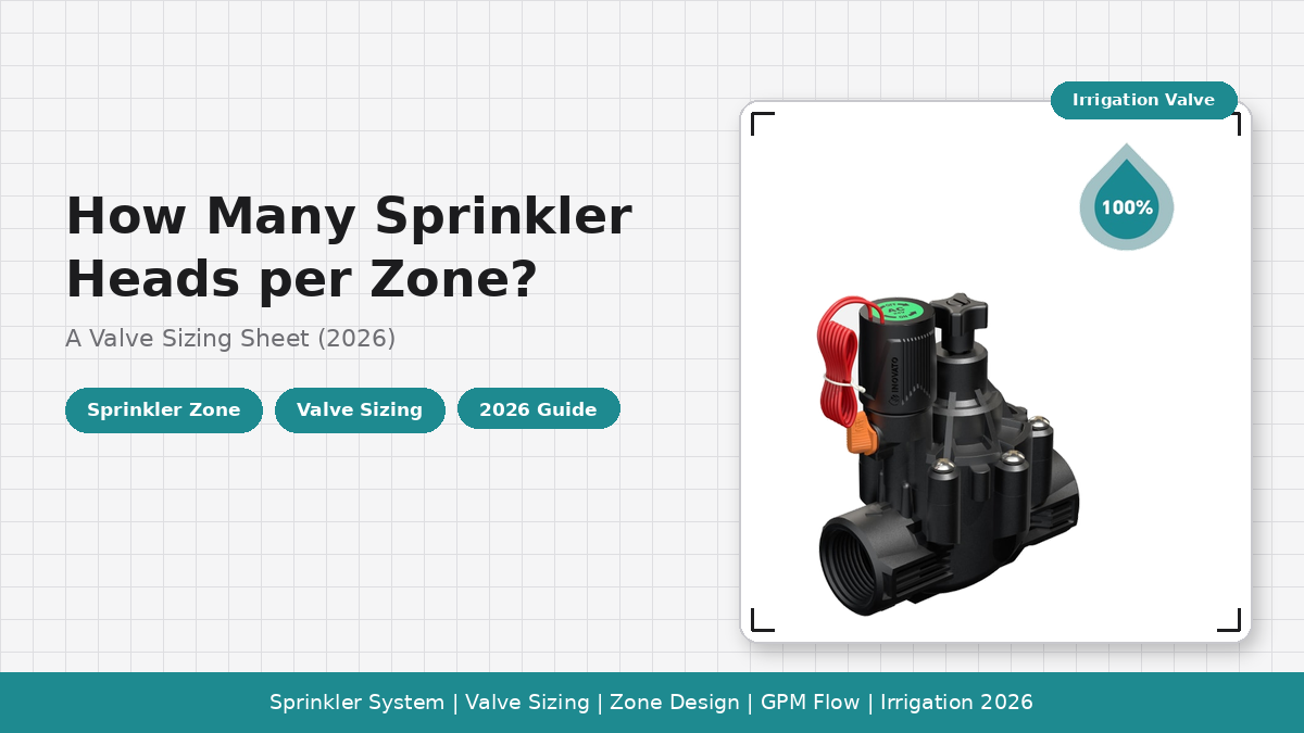
If your controller's transformer is rated for 750 mA total output and you have four zones running simultaneously on a staggered schedule, the combined holding current is roughly 0.76 A at 60 Hz — right at the edge of the transformer capacity. This is why INOVATO's T-type solenoid valves and TTV-series replacement coils are designed with a conservative 350 mA inrush and 190 mA holding target at 60 Hz, keeping per-zone load within reach of standard controllers.
One detail I rarely see in manufacturer literature: the plunger diameter varies by as little as 0.15 mm between brands. A Hunter PGV plunger measures 6.35 mm; a Rain Bird DV plunger is 6.50 mm. That tiny difference means a Rain Bird plunger can bind in a Hunter coil core tube if the plastic has swelled from moisture. So when I swap a coil across brands, I always test the plunger fit before reassembling — a habit that has saved me at least a dozen return trips.
The Physics of Inrush vs. Holding: Why the Current Drops
Understanding why inrush current differs from holding current is the single most useful electrical concept for diagnosing solenoid problems without any test equipment beyond a multimeter.
A solenoid coil is an inductor. When you first apply 24V AC, the plunger is at rest — sitting outside the coil's magnetic core. At this position, the coil's inductance is low, typically 60–70 mH. The AC impedance is dominated by this low inductance plus the DC resistance, so the current spikes high — that is your inrush, typically 350–480 mA depending on brand.
Within 50 to 100 milliseconds, the magnetic field pulls the plunger into the center of the coil. As the plunger moves into the core, the inductance jumps to 180–200 mH — roughly three times the initial value. Now the AC impedance is much higher, and the current drops to the holding level of 190–250 mA. The holding current is just enough to keep the plunger seated against the spring force.
This is why a physically stuck plunger is so destructive. If the plunger cannot move due to rust, debris, or swelled plastic, the inductance never rises, and the coil draws inrush current continuously. At 400 mA sustained instead of 200 mA, power dissipation doubles from roughly 2.4 watts to 4.8 watts. That extra heat builds up over 15–30 minutes, degrading the enamel wire insulation until it fails. I have opened failed solenoids where the internal temperature was high enough to melt the solder at the lead connections.
Solenoid Coil Burnout Diagnosis: A Five-Step Field Procedure
I have replaced hundreds of failed solenoid coils over a decade of running irrigation maintenance operations, and in roughly 70% of cases the root cause was not a manufacturing defect — it was electrical stress from undersized transformers, water ingress, or a stuck plunger causing continuous inrush draw. Here is the diagnostic sequence I teach every new technician. Following it cut our callback rate from 12% to under 3% within six months.
Step 1: Visual Inspection — The Ten-Second Check
Look at the coil assembly with a bright flashlight. A bulging or cracked plastic housing means the internal winding has overheated to the point where the encapsulation expanded and fractured. Black soot around the coil base indicates internal arcing between turns. If either condition is present, the coil is dead — move straight to replacement. Also check the wire leads where they enter the housing: the copper bundle there is work-hardened by thermal cycling and vibration, and I have seen leads that looked intact but had completely snapped inside the insulation at the entry point.
Step 2: Resistance Measurement with a Multimeter
A healthy 24V AC solenoid coil should measure between 20 and 60 ohms across its two leads, and the reading should be stable — not drifting. Set your multimeter to ohms, disconnect both solenoid wires from the controller terminals, and probe the leads directly.
- 0–5 ohms: Direct short — inter-turn insulation has broken down from thermal or moisture stress. The coil will overheat rapidly even if it still opens the valve.
- Infinite (OL): Open circuit — the copper winding has snapped, usually at the internal lead-to-winding junction where mechanical stress is highest.
- 20–60 ohms but unstable: Intermittent connection — a partially broken wire is making and breaking contact. Replace preemptively.
- 20–60 ohms, stable: DC resistance passes, but you still need to check insulation integrity in Step 3.
Step 3: Insulation Resistance Test
The insulation between the coil winding and the grounded metal core must exceed 10 megohms at 500V DC for reliable long-term operation in an underground valve box. Use a megger (insulation tester) — a standard multimeter's 9V battery cannot stress the insulation enough to reveal weaknesses. Connect one megger lead to either solenoid wire and the other to the metal plunger tube or valve body ground.
- Above 10 MΩ: Good insulation.
- 1–10 MΩ: Marginal — moisture ingress has begun. The coil may survive the current season but schedule replacement.
- Below 1 MΩ: Failed — the enamel coating has absorbed moisture. The coil will short to ground within weeks. A $40 pocket megger has saved me from reinstalling borderline coils that would have failed during the warranty period.
Step 4: Dynamic Current Draw Test
Reconnect the solenoid and put your multimeter in AC ammeter mode — a clamp-style ammeter is ideal. Activate the zone manually.
- Normal: Inrush spike of 350–480 mA for 50–100 ms, then a clean drop to 190–250 mA.
- Current stays at inrush level for over 200 ms: Plunger is stuck — the holding impedance is not developing.
- Holding current below 100 mA: Partial short reducing effective inductance — the coil will not operate the valve reliably.
- Current fluctuates during holding: Plunger chattering — debris on the sealing face or insufficient magnetic force. Produces a distinctive buzzing sound.
Step 5: Mechanical Plunger Inspection
Remove the coil and pull the plunger assembly out with needle-nose pliers. A plunger showing corrosion pitting, mineral scale, or rubbery residue from diaphragm degradation will cause erratic operation regardless of coil condition. Clean the core tube interior with isopropyl alcohol. Replace the plunger if the O-ring is flattened or the sealing face has scratches deeper than 0.1 mm. I always carry spare plungers from each major brand — they cost about $2 each from INOVATO's OEM parts list, and replacing one alongside the coil eliminates the second most common cause of valve failure.
Bulk Replacement Strategy: Why Volume Pricing and Consistency Matter
For landscape maintenance crews managing 50 to 500 valves across multiple commercial sites, wholesale solenoid coil procurement is an operational necessity. Here is the pricing breakdown when sourcing directly from an OEM manufacturer like INOVATO compared to retail.
| Order Quantity | Est. Unit Price (USD) | Typical Retail Price | Savings per Unit | Annual Savings (50 valves replaced) |
|---|---|---|---|---|
| 50 pcs | $3.20 – $3.80 | $8 – $15 | 56–75% | $240 – $560 |
| 100 pcs | $2.60 – $3.20 | $8 – $15 | 64–79% | $540 – $1,180 |
| 500 pcs | $1.80 – $2.40 | $8 – $15 | 76–84% | $3,100 – $6,300 |
| 1,000+ pcs | $1.40 – $1.80 | $8 – $15 | 82–88% | $6,600 – $13,600 |
The most overlooked benefit of bulk ordering is electrical parameter consistency across the entire inventory. When a manufacturer winds a production run of 500 coils, every coil comes from the same spool of magnet wire, wound on the same machine with the same tension settings. The batch-to-batch variance for INOVATO's TTV-series coils is under ±3% for DC resistance and under ±5% for inductance. Compare that to buying retail coils piecemeal over three months, where you might get a 24-ohm coil from one shipment and a 35-ohm coil from another. That 11-ohm difference translates to a 30% variation in holding current — enough to cause inconsistent valve behavior across zones.
Browse the full INOVATO irrigation product catalog for solenoid valve assemblies, replacement TTV-series coils, and supporting components — all shipped with factory-certified electrical test reports available on request.
Four-Step Coil Replacement Procedure for Field Crews
Step 1: Shut Down and Electrically Isolate
Turn off the irrigation controller at the main breaker. Do not rely on the controller's internal "off" setting — the triac output stage can still leak enough voltage to create a shock hazard in damp conditions. 24V AC can still deliver a painful shock when your hands are wet from working inside a muddy valve box. Remove both solenoid wires from the controller terminal strip and label them.
Step 2: Remove the Existing Coil
Unscrew the knurled retaining nut (or loosen the compression ring on Rain Bird DV models). Lift the coil straight upward off the core tube. If it resists, use a coil puller tool or gently rock the coil side to side — do not pry with a screwdriver. I have seen screwdriver gouges on valve body threads that caused intermittent leaks requiring multiple visits to diagnose.
Step 3: Pre-Installation Verification
Measure the new coil's DC resistance. If it reads outside the 20–60 ohm range, reject it — a 12V coil reads about 10 ohms and a 48V coil reads about 80 ohms, and they look identical externally. Drop the plunger into the new coil's core tube and tilt it — the plunger should fall out under its own weight. If it sticks, the coil is not mechanically compatible with that plunger diameter.
Step 4: Install, Wire, and Validate
Slide the new coil onto the core tube until it seats fully. Tighten the retaining nut hand-tight plus a quarter turn — overtightening cracks the plastic housing. Reconnect the wires and restore power. Measure the holding current at the controller end: it should stabilize at the chart values within one to two seconds. If the current stays high or the valve does not open, you caught the problem while your tools are still in your hands instead of on the way back to the shop.
Frequency-Specific Behavior: 50 Hz vs. 60 Hz
Line frequency directly affects solenoid coil performance because inductive reactance depends on frequency. A coil operating at 60 Hz has approximately 20% higher inductive reactance than the same coil at 50 Hz, meaning lower current draw and cooler operation at 60 Hz.
Using a 50 Hz-rated coil on a 60 Hz supply (the safe direction) results in roughly 10% lower current than rated values — the coil runs cooler and the valve operates safely. But using a 60 Hz-rated coil on a 50 Hz supply increases current by 10–15%, and the coil runs hotter. In marginal installations — thin-gauge wire runs exceeding 200 meters or multiple valves on a single transformer — that extra thermal stress can push the coil past its insulation temperature rating.
INOVATO's TTV-series replacement coils are factory-tested at both 50 Hz and 60 Hz, with published specifications covering both frequencies — an important qualification for crews working across different regions or importing equipment from multiple markets.
FAQ: Common Solenoid Coil Replacement Questions
Can I use a 24V DC solenoid coil in a 24V AC irrigation controller system?
Absolutely not. A 24V DC solenoid coil lacks the inductive reactance that limits AC holding current. When you apply 24V AC to a DC-rated coil, the impedance is nearly purely resistive — typically 15–25 ohms. At 24V AC across a 20-ohm coil, the current is approximately 1.2 amperes — four to six times the normal holding current. Power dissipation jumps from roughly 2.5 watts to 18–24 watts. The coil will reach 120°C within minutes, the insulation will melt, the plastic housing will crack, and the winding will short to ground.
I have personally seen this mistake destroy an entire eight-zone manifold in a single afternoon. The maintenance supervisor bought a case of "24V universal solenoids" from an online surplus seller. They were 24V DC latching solenoids intended for battery controllers. By the end of the day, five coils had failed, the transformer had tripped its thermal breaker four times, and three valve bodies were damaged by conducted heat. The total repair cost exceeded $600.
If you need battery-powered operation, use a dedicated DC latching solenoid from Hunter (SVC-compatible series) or Rain Bird (TBOS series). These use a permanent magnet to hold the plunger and consume power only during the transition pulse — a completely different architecture from AC coils.
What happens if I use a 50 Hz coil on a 60 Hz system?
Using a 50 Hz-rated coil on a 60 Hz supply is generally safe — the current will be 5–10% below rated values because inductive reactance is higher at 60 Hz. The valve will open slightly slower but operate reliably. The hazardous direction is 60 Hz coil on 50 Hz supply: current increases, the coil runs hotter. Always use the lower-frequency-rated coil on the higher-frequency supply, never the reverse.
How do I know if a solenoid coil failure was caused by the controller?
If multiple coils fail on the same controller within a short period, suspect the controller — specifically the transformer or triac output stage. Measure the AC voltage between the zone terminal and common while the controller is active. A healthy controller outputs 24V AC ± 3V. Above 28V AC means the regulator has failed — I once chased solenoid failures on a golf course for an entire summer before discovering the controller was outputting 32V AC. A 33% voltage excess reduced coil life from 5–7 years to 4–6 months. The controller replacement cost $400; the solenoid replacements had already cost over $1,200 in parts and labor.
Can I solder a broken solenoid wire instead of replacing the whole coil?
In a genuine emergency, yes — but only if the break is in the external lead wire, not inside the winding encapsulation. Cut back to clean copper, strip 6 mm, solder on 18 AWG stranded wire, and seal with adhesive-lined heat-shrink tubing. However, this repair will not pass a UL or CE moisture test and should not be permanent. Order a proper replacement and schedule the swap within 30 days.
What is the typical lifespan of a 24V AC solenoid coil in commercial service?
Under normal conditions — clean power supply, dry valve boxes, proper transformer sizing — a quality 24V AC solenoid coil lasts 5–8 years in residential use and 3–5 years in commercial service with frequent cycling. Factors that shorten lifespan include: continuous partial activation from low water pressure, voltage surges, chemical exposure from fertilizer injection, and physical damage from valve box cover impacts. For commercial contracts, I recommend proactive replacement in the fourth year of service, keeping the old units as emergency spares in the truck.
Authoritative External References
- Hunter Industries — PGV Valve solenoid specifications and maximum wire distance: Hunter PGV valve specification sheet via DripDepot (PDF)
- Rain Bird Corporation — Turf Catalog 2018: Valve electrical data including coil resistance, inrush, and holding current: Rain Bird valve technical specifications (PDF)
- OpenThings — Technical analysis of 24V AC sprinkler solenoid electrical physics with measured inductance data: Understanding 24VAC sprinkler valves
- ASTM International — B117 Salt Spray Testing standard, relevant to evaluating solenoid coil corrosion resistance: ASTM B117-19 Standard
- INOVATO OEM Custom Coil Manufacturing — 8-step customization process: INOVATO Customization Process
- INOVATO T-Type Solenoid Valves — TTV series valves and replacement coils: INOVATO T-type solenoid valve product page
- INOVATO Full Product Catalog — Complete range: INOVATO products and solutions