


How Many Sprinkler Heads per Zone? A Valve Sizing Sheet (2026)
If you have ever asked a forum "how many sprinkler heads per zone can I put on one valve," you have already seen the answers: "six rotors," "eight rotors," "depends on the valve," and the ever-popular "just add another zone." None of those answers is wrong on its own, but none of them is a calculation either.
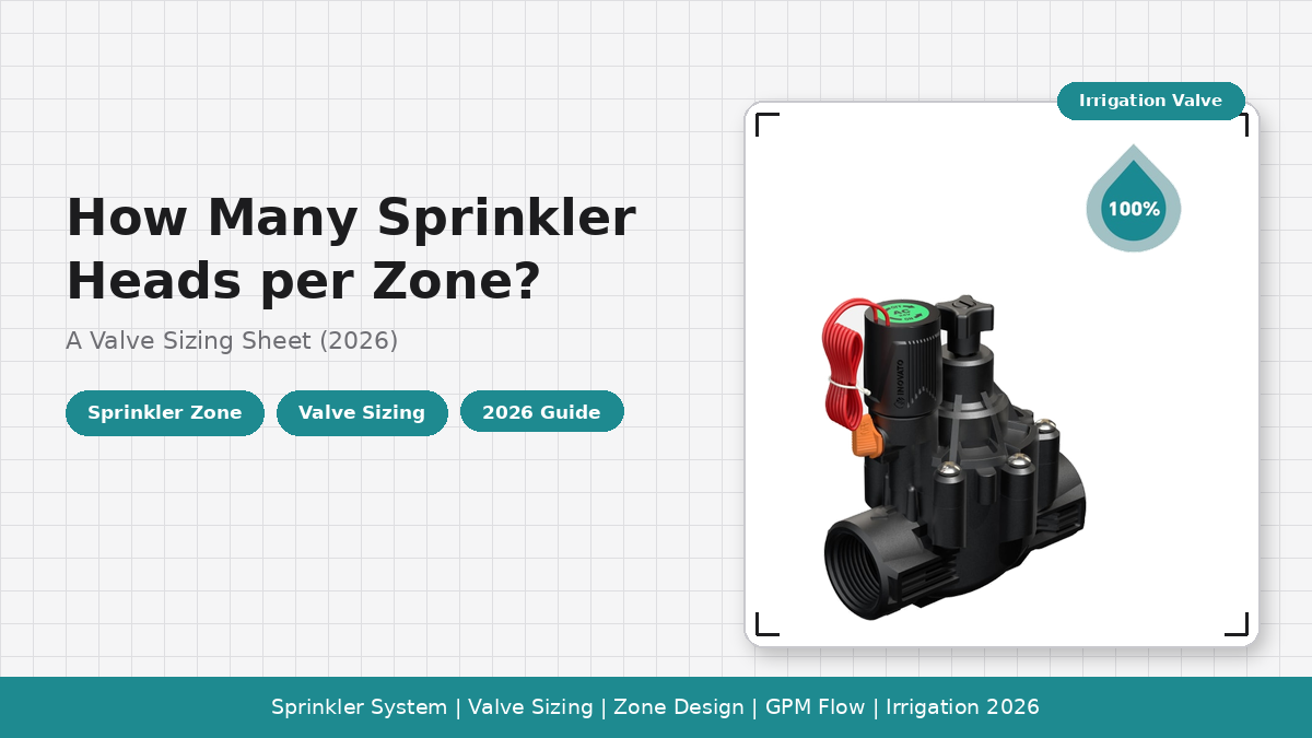
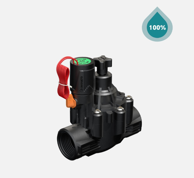
What follows is the calculation, end to end, applied to a real valve family — the INOVATO T-Type solenoid valve family, with the YT210-3/4" and 1" valve as the worked example. The same logic applies to almost any 24 VAC solenoid valve on the market, but using a single product as the reference keeps the numbers honest. Because sprinkler heads per zone is a chain of four coupled decisions — nozzle type, per-nozzle flow, total zone GPM, and valve flow window — skipping any one of them produces a zone that either under-waters the corners or pops the valve diaphragm within two seasons.
The Reference Zone: Inputs That Drive Everything Else
To make the math concrete, this sizing sheet uses a single residential zone from start to finish. The numbers below are the ones I will carry through every later section, so you can swap in your own at each step and re-derive a result.
| Parameter | Reference Value | Where to Find Yours |
|---|---|---|
| Zone area | 1,500 sq ft (roughly 139 m², a typical front lawn) | Length × width of the irrigated area |
| Nozzle family | Gear-driven residential rotor, mid-range nozzle | Manufacturer catalog at design pressure |
| Per-nozzle flow at design pressure | 3.0 GPM at 35 PSI (about 11.4 L/min at 2.4 bar) | Nozzle chart at the actual zone pressure, not at the rating |
| Static pressure at the backflow preventer | 50 PSI (about 3.4 bar) | Pressure gauge on the test port |
| Design pressure at the nozzle | 30 to 35 PSI after friction loss | Static pressure minus lateral friction and elevation |
| Spacing pattern | Triangular, head-to-head at 22 to 25 ft | Manufacturer spacing recommendation |
| Water source | Residential municipal supply, single-family tap | Meter size, service line size |
| Available flow at the tap | About 12 to 15 GPM at design pressure | Bucket test or flow meter at the backflow |
Step 1 — Choose the Nozzle Family and Read the Flow Chart
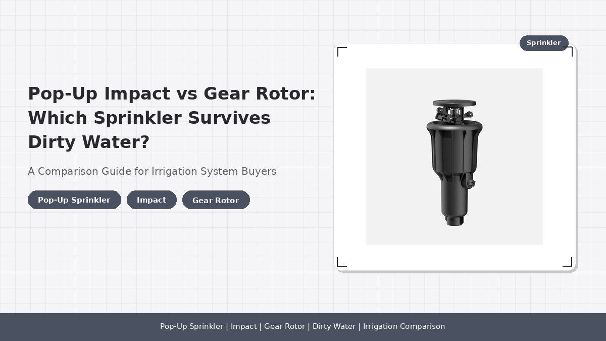
The first decision is not "which valve do I use." It is "which nozzle family am I actually installing," because the per-head flow rate of a fixed spray and a gear-driven rotor differ by a factor of about two to three at the same pressure. A residential fixed spray at 30 PSI typically uses 1.0 to 1.5 GPM per nozzle, while a mid-range residential rotor at 35 PSI uses 2.5 to 3.5 GPM per head. A high-flow commercial rotor can reach 4.0 to 6.0 GPM per head and forces a different valve size class entirely.
Reading the right flow number matters. Manufacturer catalogs publish a flow chart that lists GPM as a function of pressure and nozzle radius. Use the GPM at the design pressure (the pressure at the nozzle after friction loss), not at the static pressure at the backflow. For our reference zone at 35 PSI design pressure and a mid-range rotor nozzle, the per-head flow is 3.0 GPM. For a fixed spray at 30 PSI in the same zone, the per-head flow drops to roughly 1.2 GPM. Because the same zone can support roughly 2.5 times more spray heads than rotors at the same valve size, picking the nozzle family first is what determines the head count, not the valve model.
Residential fixed spray, 30 PSI → 1.2 GPM per head
Commercial rotor, high-flow nozzle, 50 PSI → 4.5 GPM per head
For international readers working in metric units, the conversion is 1 GPM = 3.785 L/min. The 3.0 GPM rotor above is 11.4 L/min, and the 1.2 GPM spray is 4.5 L/min. The math below works the same way in either unit system.
Step 2 — Convert Zone Area into a Starting Head Count
The next move is to translate the zone's square footage into a starting head-count range, using the head-to-head spacing rule that the nozzle manufacturer publishes. The rule is straightforward: each head must throw far enough to reach the adjacent head, so coverage on the corners is not left to luck.
- Fixed sprays are typically spaced head-to-head on 8 to 15 ft squares, which gives roughly 100 to 200 sq ft per head of effective coverage.
- Mid-range residential rotors are typically spaced on 20 to 30 ft triangles, which gives roughly 250 to 400 sq ft per head of effective coverage.
- High-flow commercial rotors push spacing to 35 to 50 ft and reach 500 to 800 sq ft per head, but they demand a flow window only larger valves can deliver.
For our 1,500 sq ft reference zone, the starting head count works out to 4 to 6 rotors or 8 to 15 fixed sprays. These are geometry-only counts; they assume ideal head-to-head coverage and a uniform zone. Real zones almost always need one or two heads in addition to handle odd corners, narrow side strips, and the inevitable overspray conflicts with hardscape. Because odd corners usually add 1 to 2 heads on top of the geometry-only count, the practical head-count budget is roughly one head higher than the geometric minimum.
Step 3 — Multiply Heads by Per-Head Flow to Get Total GPM
Now the geometry-only head count becomes a flow number. Multiply the head count by the per-head flow from Step 1:
Spray zone: 10 heads × 1.2 GPM/head = 12 GPM
High-flow commercial rotor zone: 4 heads × 4.5 GPM/head = 18 GPM
For our reference zone with rotors at 3.0 GPM per head, the total flow lands at about 15 GPM. That number is the one that has to fit inside the valve's safe operating flow window with a margin.
Step 4 — Match the Total GPM to the Valve Flow Window
The valve's published flow window is the bracket the total zone flow has to sit inside. For the INOVATO YT210 solenoid valve family, the published flow range is 2.8 to 33 m³/h, which is about 12.3 to 145 GPM across the family. The full family covers a very wide window because it includes 1/2", 3/4", 1", 1-1/2", and 2" body sizes. The two sizes relevant to residential zones are 3/4" (DN20) and 1" (DN25), and their individual safe operating windows are narrower than the family-wide figure.
| YT210 Body Size | Recommended Pressure | Family-Wide Flow Range | Practical Residential Design Flow |
|---|---|---|---|
| 3/4" (DN20) | 0.069 to 1 MPa / 10 to 145 PSI | 2.8 to 33 m³/h (12.3 to 145 GPM) | Up to about 10 GPM |
| 1" (DN25) | 0.069 to 1 MPa / 10 to 145 PSI | 2.8 to 33 m³/h (12.3 to 145 GPM) | Up to about 22 GPM |
| 1-1/2" and 2" | 0.069 to 1 MPa / 10 to 145 PSI | 2.8 to 33 m³/h (12.3 to 145 GPM) | Above 22 GPM, light commercial |
The "practical residential design flow" column is not a number we made up — it is the working window that field experience with hydraulically driven diaphragm valves of this body geometry supports at typical residential pressures. Operating above it for sustained periods pushes the diaphragm toward the upper edge of its travel and shortens service life. Operating consistently below it (below about 12 GPM on the YT210 family) can also cause issues, because the diaphragm does not always fully open at very low flows.
Step 5 — Back-Solve for the Head Count from the Valve
Now the sizing question flips around. We know the valve's safe design flow, and we want to know how many heads the valve can feed:
Rotor zone (3.0 GPM/head): 10 ÷ 3.0 = 3.3 → 3 heads, design point
Spray zone (1.2 GPM/head): 10 ÷ 1.2 = 8.3 → 8 heads, design point
1" YT210 @ 22 GPM safe design flow:
Rotor zone (3.0 GPM/head): 22 ÷ 3.0 = 7.3 → 7 heads, design point
Spray zone (1.2 GPM/head): 22 ÷ 1.2 = 18.3 → 14 heads, design point (rounded down with margin)
The valve-first calculation is the more honest of the two approaches, because it bakes the valve's real-world limits into the answer before the geometry-only count has a chance to drift. For a quick rule of thumb that you can keep in your head on a job site:
| Valve Body | Rotors (mid-range, 3.0 GPM) | Fixed Sprays (1.2 GPM) | Drip-heavy Mixed Zone |
|---|---|---|---|
| 3/4" YT210 | 3 to 4 heads | 6 to 8 heads | Yes, up to about 8 GPM drip |
| 1" YT210 | 5 to 7 heads | 10 to 14 heads | Yes, up to about 15 GPM drip |
| 1-1/2" YT210 | 10 to 14 heads | 20 to 28 heads | Rarely the right pick for drip |
| 2" YT210 | 16 to 22 heads | 30 to 40 heads | Use manifolded drip instead |
For comparison, the broader INOVATO T-Type solenoid valve family covers the same flow window in five body sizes, so the same logic extends to commercial sites where a single zone can run 20 to 40 rotors at once. The 3/4" and 1" pair just happens to be the sweet spot for residential.
Step 6 — Verify Pressure at the Last Head
The most common reason a sprinkler zone underperforms is not the head count — it is pressure starvation at the last head in the run. Every foot of lateral pipe, every swing joint, and the valve itself eats a little pressure. By the time water reaches the farthest head, the design pressure can be substantially lower than at the backflow preventer.
The reference zone's static pressure is 50 PSI at the backflow. After a typical residential run — say 60 ft of 1" Class 200 PVC lateral, three swing joints, and a YT210 valve that drops about 2 to 3 PSI at full flow — the design pressure at the last head lands somewhere around 38 to 42 PSI for rotors near the valve, and 32 to 36 PSI for the last head in the run. Both are inside the rotor's published operating range of about 25 to 65 PSI, so the design holds. If the farthest head had instead dropped below 25 PSI, the right move would have been to drop one head from the zone, not to upsize the valve.
How the Sizing Sheet Changes for Different Zone Types
The same six-step logic applies to almost any zone, but the head-count band shifts with the nozzle family, the available tap flow, and the design pressure. Here is how the result changes for the four most common residential and light-commercial scenarios:
| Zone Type | Nozzle Family | Typical GPM/Head | Right Valve | Typical Head Count |
|---|---|---|---|---|
| Small front lawn strip | Fixed spray, 8 to 12 ft spacing | 1.0 to 1.5 GPM | 3/4" YT210 | 6 to 8 heads |
| Typical residential lawn | Mid-range rotor, 22 to 25 ft spacing | 2.5 to 3.5 GPM | 1" YT210 | 5 to 7 heads |
| Large residential or small commercial lawn | High-flow rotor, 30 to 40 ft spacing | 3.5 to 5.0 GPM | 1" YT210 or 1-1/2" YT210 | 4 to 6 heads on 1", 8 to 12 on 1-1/2" |
| Drip-heavy mixed planting bed | Dripline emitters, 1.0 to 2.0 GPH | About 0.05 to 0.1 GPM per emitter | 3/4" YT210 with pressure regulator | 100 to 200 emitters, manifolded |
"When a residential zone fails, it is almost never the nozzle's fault. It is either too many heads for the valve, too little pressure at the last head, or both. Run the six-step sheet and the failure modes usually show up before the first trench is dug." — INOVATO irrigation valve engineering desk
For buyers comparing valve options before placing a procurement order, the INOVATO valve category page shows the full T-Type family with the matching solenoid, regulator, and filter accessories for each body size. The selection-guide companion article at YT210 solenoid valve for irrigation systems: a pressure and flow selection guide walks through the pressure-flow trade-offs in more detail.
Common Sizing Mistakes and How to Avoid Them
- Counting heads instead of GPM. A 6-head rotor zone can easily exceed a 3/4" valve's safe flow, and a 12-head spray zone can fit comfortably inside one. The head count is downstream of the GPM, not the other way around.
- Reading the flow chart at the wrong pressure. Manufacturer catalogs publish GPM at the rated pressure (often 30 PSI for sprays, 45 PSI for rotors). Use the design pressure at the nozzle, not at the backflow, because the actual operating pressure is usually lower after friction loss.
- Ignoring the meter size. A 5/8" residential meter typically maxes out around 15 to 20 GPM for the whole property. Two zones running at once can starve each other even if each zone is correctly sized for its valve.
- Forgetting head-to-head coverage. Adding heads "for safety" without checking spacing creates a zone where the corners are over-watered and the middle is under-watered, and the symptom looks like a nozzle problem.
- Putting drip and spray on the same valve. They need different pressures and different run times. A drip-heavy mixed zone belongs on its own valve, almost always a 3/4" body with a pressure regulator.
Industry Standards and Authoritative References
Residential and light-commercial sprinkler zone sizing has converged on a small number of public references. If your installer or OEM cannot anchor their sizing recommendations to one of these, you have no way to verify the design.
- Landscape irrigation scheduling — EPA WaterSense publishes the WaterSense Labeled Irrigation Controller specification that any controller-based zone timing should be checked against; the program also publishes a water-budget tool that turns zone area and nozzle type into a weekly runtime.
- Standard for landscape irrigation emission devices — ASABE/ICC 802-2014 is the joint ASABE / International Code Council standard for landscape irrigation emission devices and defines the test methods that Sprinkler Nozzle catalogs use to publish their flow and radius data.
- Backflow and cross-connection control — Foundation for Cross-Connection Control and Hydraulic Research at USC publishes the Manual of Cross-Connection Control that nearly every U.S. municipality references when sizing the backflow preventer upstream of a sprinkler zone.
- Uniform plumbing code for irrigation — IAPMO Uniform Plumbing Code covers the downstream plumbing side of any zone that ties into a domestic tap, including the pressure regulator and the master valve arrangement.
- Valve body geometry and flow test methods — ISO 9635:2019 is the international standard for solenoid valves used in irrigation and is the closest global reference for the YT210's published flow window of 2.8 to 33 m³/h.
Frequently Asked Questions
How many sprinkler heads can I run on one irrigation zone?
Most residential and light-commercial zones run 4 to 8 rotor heads or 6 to 12 spray heads, sized so the total zone flow lands between 6 and 15 GPM. The exact head count depends on three numbers — nozzle type, nozzle flow rate in GPM, and the valve's usable flow window — not on a single industry-wide head-count limit. A 3/4" YT210 valve comfortably feeds 4 to 6 rotors or 6 to 10 sprays at standard residential pressure; a 1" YT210 valve comfortably feeds 6 to 10 rotors or 10 to 14 sprays. Going beyond those counts pushes the zone into the next valve size.
How many GPM does a typical residential sprinkler zone use?
Most residential zones use between 6 and 15 GPM, with 8 to 12 GPM being the most common design point. Spray nozzles usually run 1.0 to 1.5 GPM each, mid-range rotors run 2.0 to 3.5 GPM each, and high-flow commercial rotors can reach 4.0 to 6.0 GPM each. The right way to size a zone is to multiply nozzle count by per-nozzle GPM, then verify the result sits inside the valve's published flow window before deciding on a head count.
How do I calculate the head count for a valve?
Take the valve's safe operating flow in GPM, divide by the per-nozzle flow rate in GPM at the design pressure, and round down to a whole number of heads. For a 1" YT210 valve with a safe design flow of about 22 GPM at typical residential pressure, that gives roughly 22 ÷ 3.0 = 7 rotors or 22 ÷ 1.2 = 18 sprays. Round down and subtract one head as a margin to leave room for future nozzle changes, so the working answer is 6 to 7 rotors or 14 to 16 sprays on a 1" valve.
Can I put too many heads on one valve?
Yes, and it is one of the most common residential irrigation failure modes. Too many heads drive the total flow above the valve's published range, which causes pressure to collapse at the last heads in the run, Misting Nozzles, uneven precipitation, and shortened valve life from sustained cavitation. The symptom is usually a zone that runs but does not throw the design radius on the farthest heads — which is almost always a hydraulic sizing problem, not a nozzle problem.
Should I use a 3/4" valve or a 1" valve for a residential sprinkler zone?
Use a 3/4" valve for small lawns, drip-heavy zones, or any zone with a total flow below about 10 GPM. Use a 1" valve for typical residential lawn zones in the 10 to 22 GPM range. Move to a 1.5" or 2" valve only when the zone flow exceeds about 22 GPM — usually a larger lawn, a commercial site, or a zone with high-flow commercial rotors. The cost difference between 3/4" and 1" is modest, but the head-count difference is real: a 1" valve typically supports 30 to 50 percent more heads than a 3/4" valve on the same mainline pressure.
What happens if a zone's flow is below the valve's minimum?
Operating consistently below the valve's minimum flow can cause the diaphragm to chatter or fail to fully open, which over time damages the seat and produces a zone that leaks through the valve after shutdown. For the YT210 family the published minimum is 2.8 m³/h, roughly 12.3 GPM; designing below that on a permanent basis shortens service life. If a zone truly needs less flow, the right fix is usually a smaller nozzle selection, not a smaller valve.